Graph Configuration
In order to visualize the data in your tables as a graph, you would need to populate the below given tables.
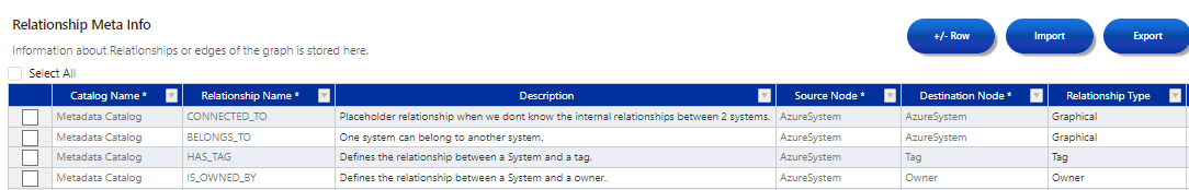
Relationship Meta Info
This table stores information about the relationships or edges of the graph.
This table includes the following columns:
| Column Name | Description | Example |
|---|---|---|
| Catalog Name | It is the name of the catalog where the relationship is to be created. | Metadata Catalog |
| Relationship Name | It is the type of relationship to be created. The relationship specified here can be used to create relationships in the Graph Relationship Table. | CONNECTED_TO |
| Description | Here we can add a description of the type of relationship. | Define the relationship between 2 systems. |
| Source Node | It is the origin node from which the relationship is to be created. | Azure System |
| Destination Node | It is the destination node where the relationship is to be established. | Azure System |
| Relationship Type | It is the type of relationship that needs to be created, such as Tags, Owner, or Graphical. | Graphical |
- To display hierarchical levels, we require a "BELONGS_TO" relationship.
- Additionally, for creating a graph, at least one graphical relationship, such as "CONNECTED_TO," must be included.
In the example given in the above table, we used the 'CONNECTED_TO' relationship between the source node (Azure System) and the destination node (Azure System), specifying the relationship type as Graphical.
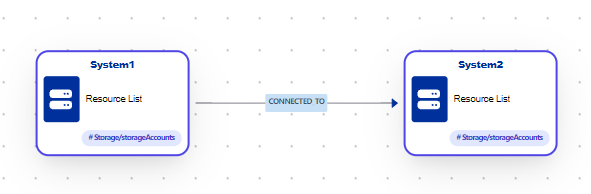
We can now establish a connection (of type: CONNECTED_TO) between the two nodes of the type Azure System. In the picture below, we connected System 1 to System 2.
The 'HAS_TAG' relationship is mandatory in order to save a graph.
[Azure Systems]-[HAS_TAG]->[Tag]
To save a graph in the Metadata Catalog for the Azure Systems Node, we need to establish a 'HAS_TAG' relationship between the source node (Azure System) and the destination node (Tag).
Best Practices
The naming convention for relationships should be Upper case using an underscore ("_") to separate the words.
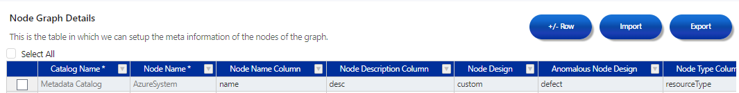
Node Graph Details
This table is utilized to configure the meta-information of the nodes within the graph and can also be referred to as a Node Design Table.
The table comprises the following columns:
| Column Name | Description |
|---|---|
| Catalog Name | Enter your Catalog Name here. |
| Node Name | Enter your Node Name here. |
| Node Name Column | Every node in the graph needs a node name. The node name will be taken from this column. |
| Node Description Column | Every node in the graph needs a description. The description of the node will be taken from this column. |
| Node Design | Replace with: Internally used. Please hardcode to: "custom". |
| Anomalous Node Design | Internally used. Please hardcode to: "defect". |
| Node Type Column | Every node in the graph needs a node type. The node type will be taken from this column. Example: A System table might have the System Types to be either Database, Service, App etc. This system type is stored in the sysType Column. |

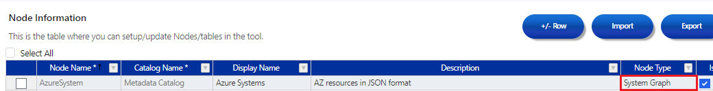
After adding an entry to the Node Graph table, change the Node Type in the Node Information Table to either "System Graph" OR "Metadata Graph.
Create the graph by selecting the relevant rows and using the 'Create Graph' option.
Entries in the Relationship Meta Info and Node Graph Details are needed for creating graphs.